Multi-Sensor-Embedded-Framework
An Arduino sensor framework — capacitive moisture, temperature, light and ultrasonic — built as a C++ object-oriented exercise, finished on a custom PCB.
The idea: Learn C++ on real hardware
This build collects and displays real-time data from several sensors on a microcontroller. The goal was not the monitoring system for its own sake: it was to build a stronger foundation in C++ — classes, encapsulation, modular code organisation — while getting hands-on with sensor interfacing, signal acquisition and the practical application of analog and digital systems in embedded engineering.
The approach: Grow the system, one sensor at a time
It went through four iterations rather than one design.
| Iteration | What changed |
|---|---|
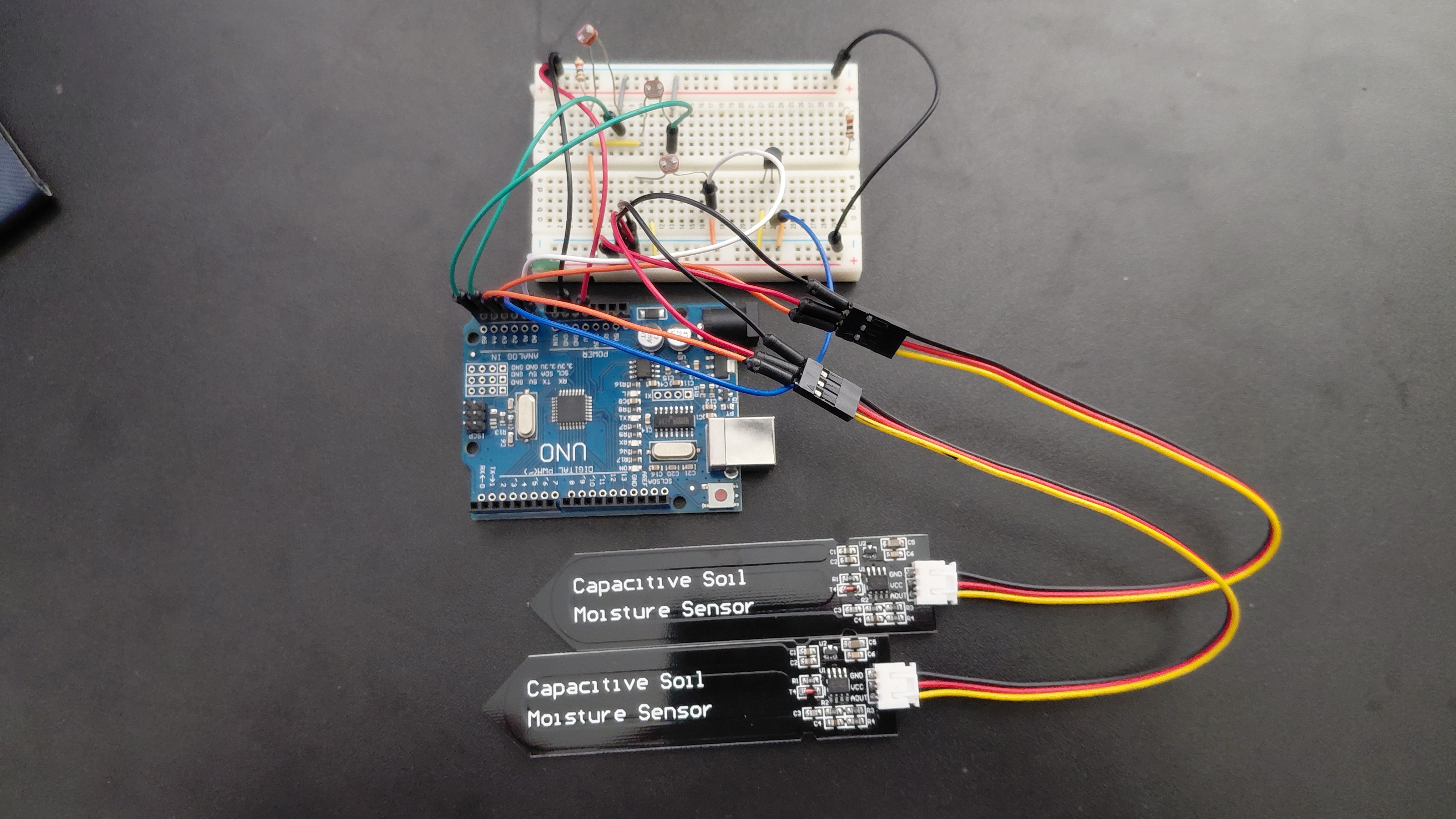
| 1 | 1 moisture sensor, 1 temperature sensor, 1 light sensor |
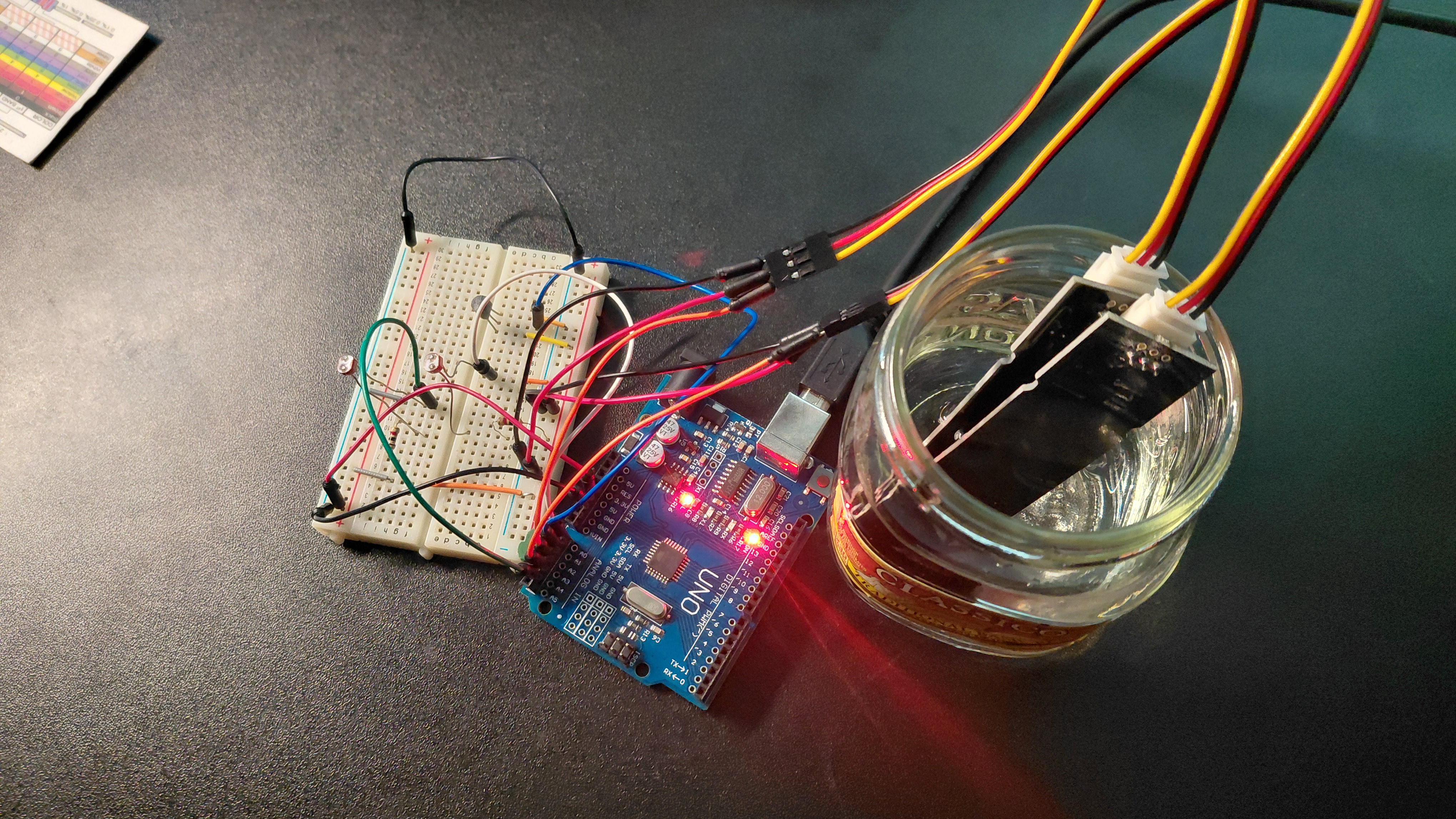
| 2–3 | More moisture, temperature and light sensors added; moisture readings tested |
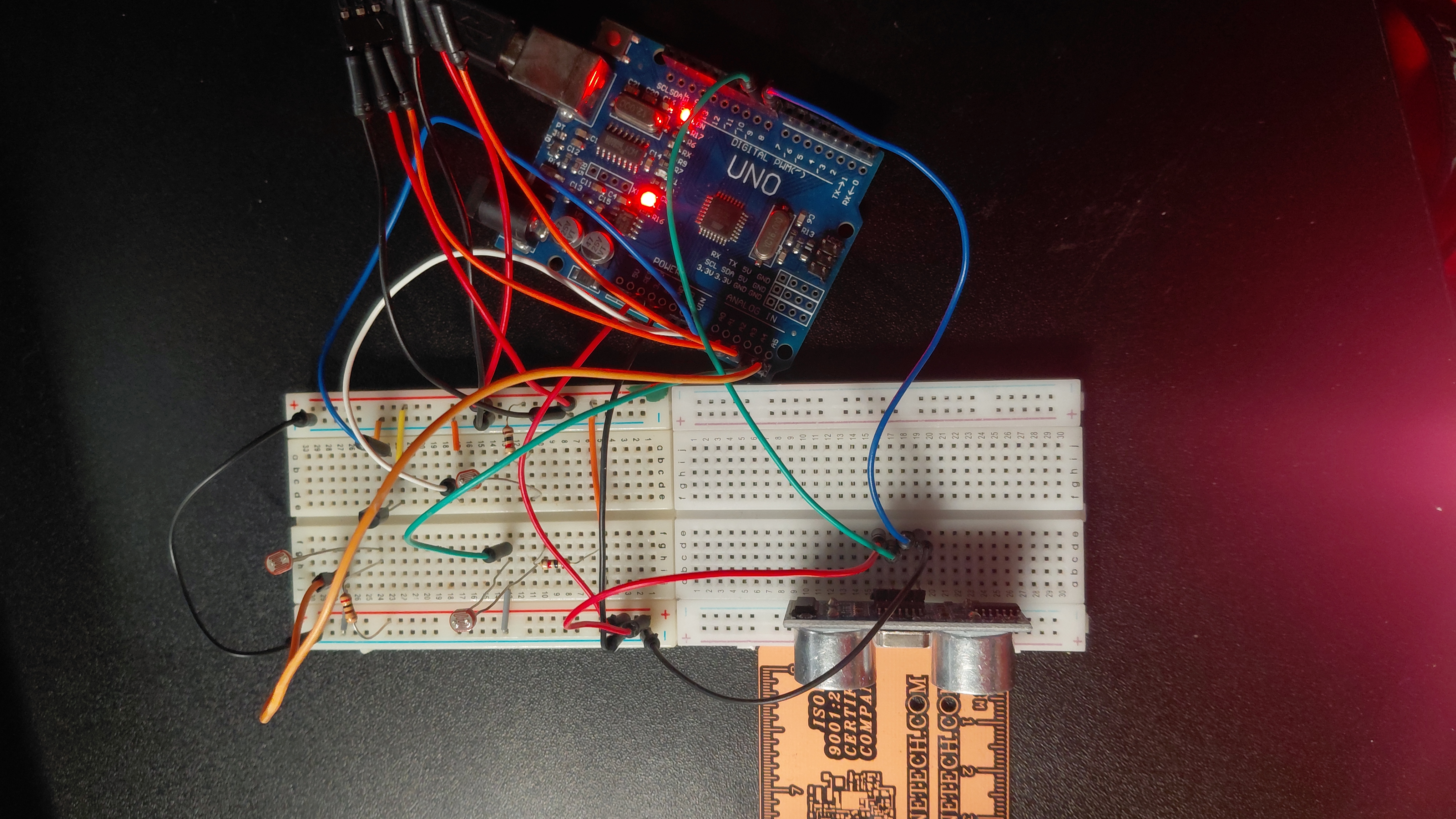
| 4 | Ultrasonic distance sensor added and tested |
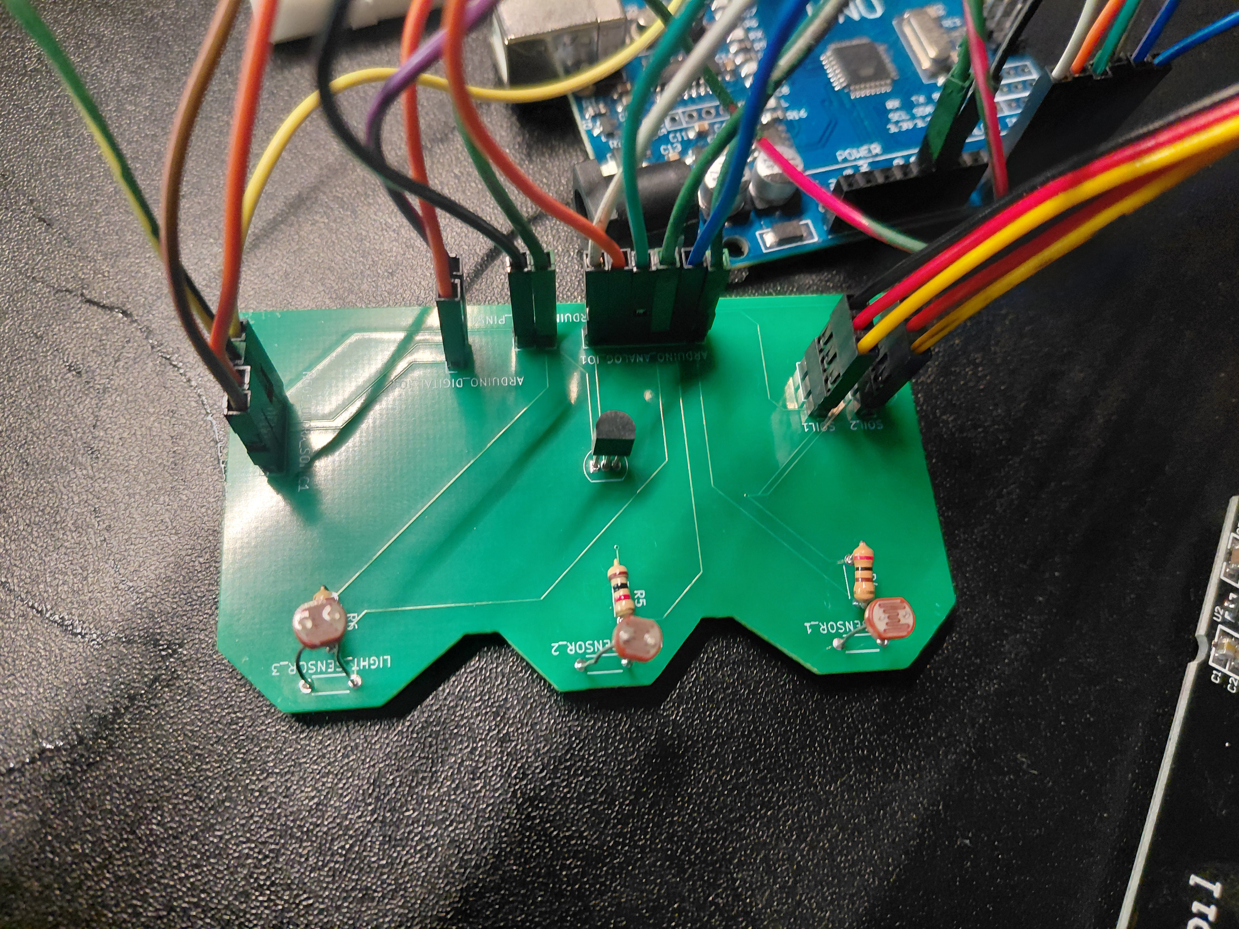
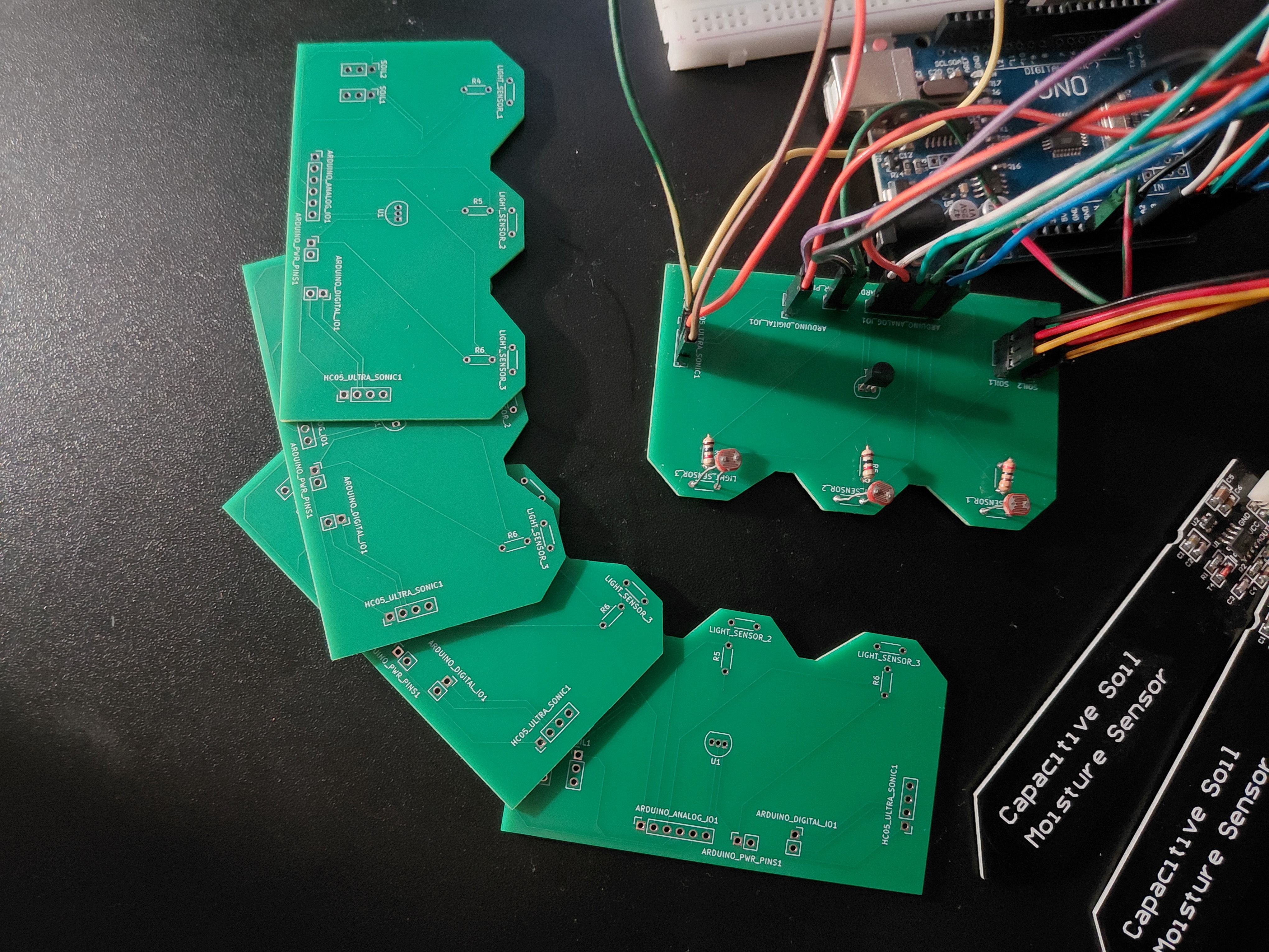
| Final | Custom printed circuit board |
Iterations 2 and 3 were about multiplicity — the same sensor types repeated — and about testing what the moisture readings actually did. Iteration 4 brought in a different interface entirely, the ultrasonic sensor, which is the point where the project stops being only about analog acquisition.
The build: A PCB to kill the wiring
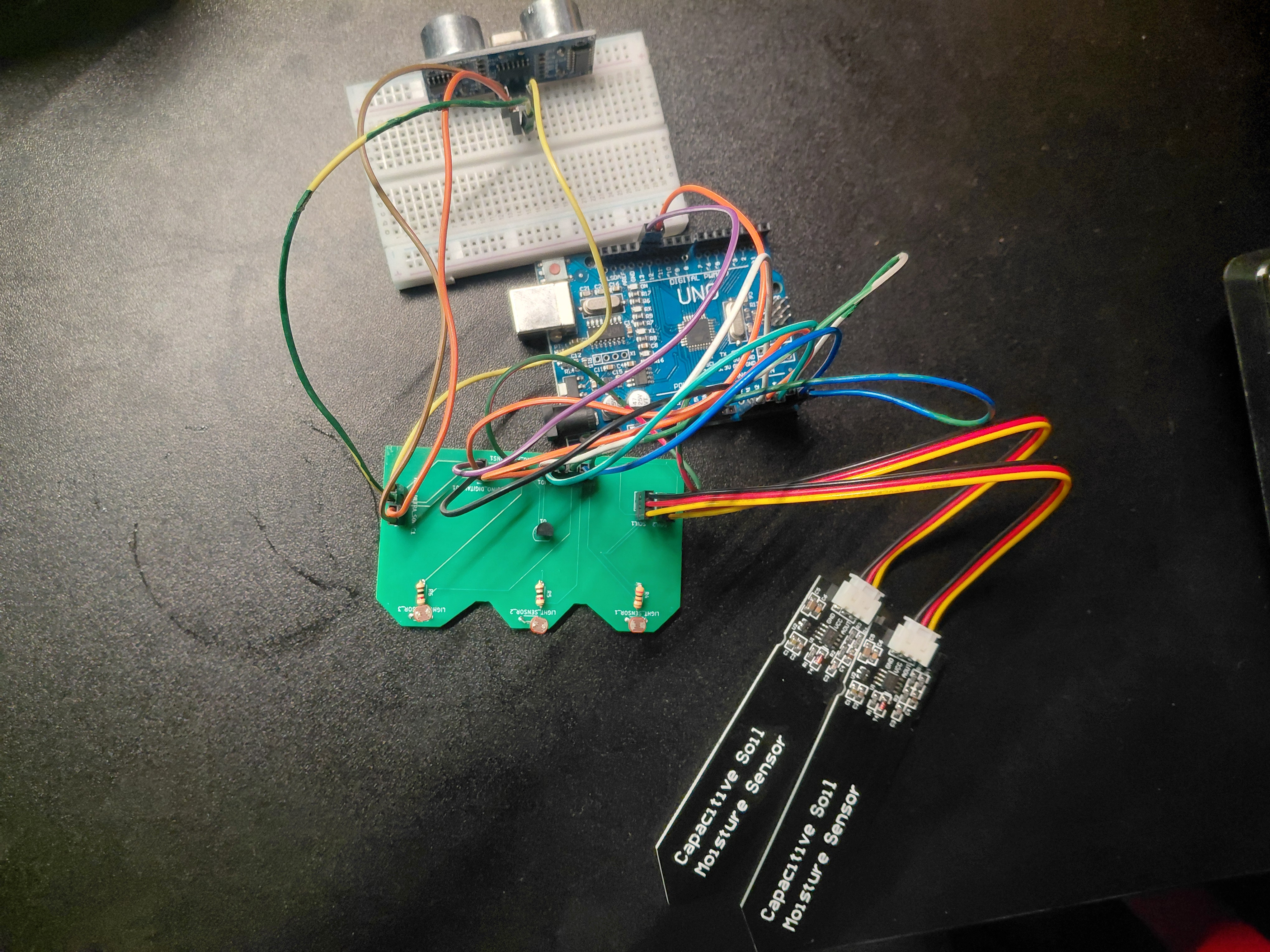
The final step was a custom printed circuit board, built to clean up the wiring that had accumulated across four iterations of sensor additions. The board’s silkscreen names its connections in full: LIGHT_SENSOR_1/2/3, C_SENSOR1/2/3/4, HC_SR04_ULTRA_SONIC1, ARDUINO_ANALOG_IO1, ARDUINO_DIGITAL_IO1 and ARDUINO_PWR_PINS1 — three light-sensor sites, four capacitive-sensor headers, one ultrasonic header, and pinouts that drop straight onto the Uno.
The result: A framework, not a product
What exists is a working multi-sensor monitoring framework with an object-oriented structure, a mixed analog and digital peripheral set, and a board that gathers it onto one piece of hardware.
There are no measured accuracy figures, sample rates or calibration results yet, so none are quoted here.
What’s next
Nothing is decided yet for a next step. What is here is the four iterations and the board — a working framework, and a starting point for the next multi-sensor build rather than a finished instrument.